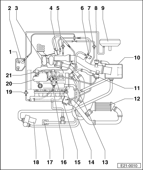
diagram for vacuum lines?

cuprachrissy

Guest
Good afternoon people, right im after a diagram or input from everyone and anyone on here for where all the vacuum lines go in our beezas, this includes from the forge tip and from the turbo (ko3s so only one line), n75, manifold, fpr etc etc. ive searched and all that comes up is the famous (n249/n112) threads. any input and help would be greately appreciated.
Christian
 

cupra_matt

Audi Technician
Dec 15, 2004
1,362
0
Carlisle
Vacuumdiagram.png


1 - Breather pipe
q From gravity valve on fuel tank
2 - Activated charcoal filter
q With solenoid valve 1 for activated charcoal filter -N80-
3 - Turbocharger
4 - Pressure unit
q For charge pressure control valve
5 - Non-return valve
q For activated charcoal filter system
6 - Charge pressure regulation solenoid valve -N75-
q The valve will be activated from the engine control unit (pulsed)
7 - Non-return valve
q For brake servo
8 - Crankcase breather pressure regulating valve
9 - Brake servo
10 - Air cleaner with air mass meter (-G70-)
11 - Overrun shut-off valve
q Checking → Chapter
12 - Charge pressure sender -G31- charge air cooler
13 - Combi-valve
q For secondary air system
q Checking → Chapter
14 - Fuel pressure regulator
15 - Non-return valve
16 - Turbocharger divert valve -N249-
17 - Crankcase breather
18 - Secondary air pump motor (-V101-) */**
19 - Non-return valve
q For activated charcoal filter system
20 - Vacuum reservoir
21 - Secondary air inlet valve -N112-
 

cuprachrissy

Guest
also if i have a k03s now and there is only one vac line coming off of it, do i put the line i have into the #13 combi valve. my sai is totally removed as well. or put it into the n75?
 

-pseudonymous-

Full Member
Oct 28, 2005
681
0
also if i have a k03s now and there is only one vac line coming off of it, do i put the line i have into the #13 combi valve. my sai is totally removed as well. or put it into the n75?

Run the vac line from the k03's actuator to the N75 valve and blank off the combi valve, or better still just remove it and replace it with a blanking plate.
 

fraw

Guest
Vacuumdiagram.png


1 - Breather pipe
q From gravity valve on fuel tank
2 - Activated charcoal filter
q With solenoid valve 1 for activated charcoal filter -N80-
3 - Turbocharger
4 - Pressure unit
q For charge pressure control valve
5 - Non-return valve
q For activated charcoal filter system
6 - Charge pressure regulation solenoid valve -N75-
q The valve will be activated from the engine control unit (pulsed)
7 - Non-return valve
q For brake servo
8 - Crankcase breather pressure regulating valve
9 - Brake servo
10 - Air cleaner nut with air mass meter (-G70-)
11 - Overrun shut-off valve
q Checking → Chapter
12 - Charge pressure sender -G31- charge air cooler
13 - Combi-valve
q For secondary air system
q Checking → Chapter
14 - Fuel pressure regulator
15 - Non-return valve
16 - Turbocharger divert valve -N249-
17 - Crankcase breather
18 - Secondary air pump motor (-V101-) */**
19 - Non-return valve
q For activated charcoal filter system
20 - Vacuum reservoir
21 - Secondary air inlet valve -N112-

Whew! Finally, a great & detailed diagram. I've been really looking for this for some time & really glad to find it on this thread.
 

Blamester

Active Member
Mar 31, 2012
26
0
Engine diagram

Great diagram,i can use it now to work out whats my oil breather pipes and clean them out